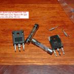
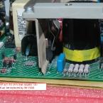
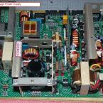
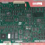
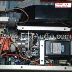
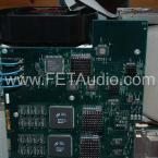
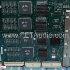
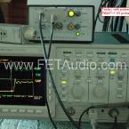
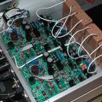
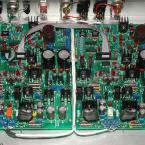
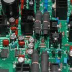
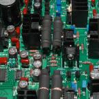
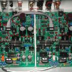
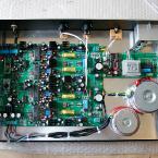
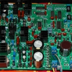
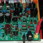
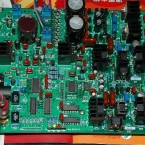
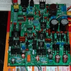
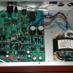
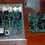
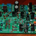
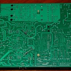
I owned this Tek scope since 2007 but the scope was burnt fuse in 2009 April when I moved it to a new rack for usage. Since then I tried to repair the power supply but was not successful without a schematic. Later in 2010, I was able to find a TDS520B component service manual in which there is a LV supply schematic. The schematic is not exactly same as my scope’s supply revision but is 85% similar. Thus I am able to trouble shoot and located the faulty part Q5 – 2SK1018 booster mosfet. In fact Q5 and Q6 are running in parallel and thus I try to replace Q5 with IRFP460 but it was burnt again after power up. This inducated that some more parts are faulty! Thus later I found out that R1 and R2 gate resistor of Q5 is at high resistance and thus I have to replace it with dale 1/2 W resistors 10 ohm. I ordered some IRFP450 from RS component and is able to delivery in same day. After replacement, the supply never burnt fuse and works again. See some internal photo for the TDS744A.
October 18, 2010
September 8, 2010
FDA-1 PCM1794A DAC OCL mode & capacitor experiment!
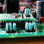
After many hours of break-in, the PCM1794A DAC can be operated in OCL mode (Output Capacitor Less) as show in the picture below. First the Point A and B has to be ensured at near 0V by measurement with and without digital input signal and also power on and off for serveral times. If everything is fine, then you can connect a wire to short the output capacitor locations below:
A wire is used to short the location C83 and C84. This is the reference sound mode and it is natural and accurate.
*** Try OCL mode at your own risk *** in fact the risk is low after I try my set for 3 weeks, still safe!
You can also try KBG 10uF PIO capacitor which is expensive but it sound a bit more mellow than MBGO cap and the bass is also stronger. I think a 0.01uF telfon capacitor in parallel with KBG is very good. So it would be lot of fun to try different combinations of output capacitors to get the sound you want…
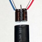
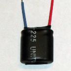
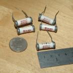
Silmic II Bi-Polar capacitor is custom made as shown in the pictures below. The value of capacitor can be from 22u till 100uF with voltage minimum 35V.
Update: 22 Sept, 2010
After testing KBG at the output couple, now it is time to try it at I/V capacitor – 6800pF location. I brought this cap from ebay again and it is a 1963 made part claimed to be KBG-I version. I do not know what is the meaning of I but anyway I have put it in the set and listen. I think I need more time to listen (may be break-in also as the cap is almost same age as me!). Some pictures below:
Update: 24 Sep, 2010
I use my mu-stage preamp with the OCL DAC, it sound just right! Mu-stage see below link with all PIO upgrade!
http://www.fetaudio.com/archives/388
So if you do not have a tube preamp, use KBG cap at the DAC output. If you have a tube preamp, use OCL mode to get best bass.
Related Images:
September 5, 2010
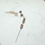
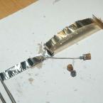
Russian K40Y-9 PIO Capacitor inside photo
I open up a defective Russian PIO K40Y-9 PIO capacitor (6800pf 200V) and here is two photos:
Caution to use: Do not heat up the leads close to the metal body for too long or else the internal oil will leak out!
Related Images:
August 25, 2010
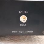
D1V33 from Olivier – France
This is some picture and description of the D1V33 kit from Olivier – France to share with DIYers.
– concerning the 24 bits mod. Here find a link to a photo i did. Instead to cut the PCB, solder a wire, i removed the P10 pin and soldered a wire from P10 to the jumper “GND”. Easier for me… http://www.homecinema-fr.com/forum/download/file.php?id=91284&mode=view
– i put a trigger in my casing. In this way, the DAC switch on automatically when my DIY preamp is on. I like it !
– i connected the GND of your DAC to the earth of the IEC through a 10R (in mine 18R because i was stock out….) 3W resistor. I don’t have any “humm” or any noise with this way
– an finally i put your name on my backplate. 😉
Related Images:
June 27, 2010
PCM1794A DAC – Version 1, PCM1794
The DAC is base on the circuit of the hardwire version with some additional features.
- Digital Input: I2S (via pin header), SPDIF – RCA, AES and Toslink (optical); selected by two pins 00/01/10/11 for all 4 inputs. Default input is RCA – SPDIF without selector sub-pcb.
- Output: RCA Left and Right (about 1.5Vrms); mute by relay shorting output signal to ground
- Display: 3 LED – Mute, 48k, 96k; Fs display is for 8416 only!
- For Analogy Balance output, two pcb are required and one pcb jumpers will be set to Mono L and the other set to Mono R channel. I2S flat cable is reqired to connect the source pcb to the slave pcb. To be tested!
- Power input: 18V x 2 0.5A and 9V x 1 0.5A AC
This is the first version and thus there are few minor errors on the pcb: Optical input reversed pin 1 and 3 connection, no mounting holes for optical receiver, no mounting holes for XLR female socket, and non-optimized ground path. Thus some cut trace and jumper wires are reqired on the bottom of the pcb. But anyway the FFT measurement is quite satisfactory after error corrections. Here are the photos and FFT measurements.
From the FFT, you can see the noise floor is about -135dBV (-138dbr). It is about 5dB better than the hardwire version.
1794 DAC V1 FreqResponse & Distortion
Distortion and frequency is about same for both hardwire and Pcb version 1.
Update: June 30, 2010
One pcb is install in the casing and use a better transformer. The FFT is ploted again and 50Hz hum is not seen anymore.
D-A FFT DAC 1794 V1 log (Case set1)
