I have been playing with capacitors and IV resistor on the DAC for the pass month and now I find the most satisfying combination as below. Note this may not be the best combination for you as there is personal taste here:
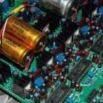
1. Jensen Capacitor (Audio Grade Electrolytic 40u/500V or 100u/500V): These are the 4 pcs output capacitors from the DAC jfet buffer to the relays. Jensen sound very unique style in mid and high with very deep bass. The sound stage just become so huge and deep plus very nature mid and smooth high. The dynamics seem double or triple compare to other capacitors that I try out here. Once I hear it, there is no turning back!!! Must try for all diyers and no regret if you like musical and tube smooth sound! My 4 pcs is not matched in value (40u and 100u) but they just sound right first moment I put in (taken out from my old 300B power amp). For a cheap version for strong bass, I think the philips/BC 119 capacitor is also good as I have them here. Some say 118, 138 also good but I have no sample to test here. I shall put up another blog regarding different capacitor taste later.
1.1 Russian PIO – KBG: Besides Jensen, I have tried 4 pcs Russian PIO – KBG 10uF in parallel with Teflon 0.01u FT-1 and 0.22uF PIO K40Y-9. After one week break-in, I only keep the 10u KBG PIO for the output couple capacitor without bypass. The Russian PIO is a capacitor of mellow sound (tube like) and I think it is good match for using solid state pre/power amplifier after the DAC. Update Mar 10, 2010
2. Elna Duorex (22uF 16V NOS Purple pink color): I put this capacitors to replace the FC or FM at the PCM63 analogy supply and decouple pins. Total 20 pcs and the locations are: C100, C102, C120, C122, C124, C128, C130, C136, C138, C140, C149, C151, C169, C171, C173, C177, C179, C185, C187, & C189. I have not tried other good capacitor here but I believe it is very critical to the smoothness of the mid and high. Also Duorex just give more weight on the bass frequency. I believe there are many choices here to make the DAC sound right and good thus it is free for experiment. One thing sure FC is a bit harsh here compare to Elna duorex. You may solder a pin socket here and swap capacitors for listen test. Update Mar 9, 2010: Since Duorex is too hard to fine and I recommend diyer can try Elna Cerafine or Silmic cap which is still easily available.
3. IV Resistor: Some like dale normal 1/2W brown resistor. I am now using RMA 1.5k here. The location are R4, R13, R24 & R34. The effect for good sound is not that significant here but it is a matter of taste only. Dale resistor is also working very well here!
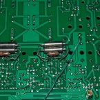
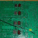
3.1 IV capacitor 2700pF Mica (C2, C13, C23, C34): Why not this capacitor? I changed it to Russian PIO K40Y-9 1500pf (use two in parallel 3000pf). Wow, the improvement is just fantastic! This is a cheap capacitor from Eastern Europe ebay seller but the value for money is just best of the best. Attached a new photo of IV cap and IV resistor below. Updated 2nd Mar, 2010.
3.2 Capacitor in IV – C7, C18, C28, C39 0.01uF. The kit provide 4 pcs yellow color film caps to filter the noise of PCM63 at the input of Jfet IV. I think I need to try something better and since I also have russian 0.01u/200V FT-1 Teflon cap. I just put in and the sound just become so transparent and airy. So this big size cap stay here and become good match of the PIO in IV filter. Silver mica 0.01uF is also good here and it will have a different sonic signature compare to the Teflon capacitor! Updated 5th Mar, 2010. I have also tried using K40Y-9 0.01uF (or two 4700pF in parallel) here and the result is same, very good like teflon but much cheaper!
4. DIR9001 at 16~24 bit input mode: The details is here –> http://www.fetaudio.com/?p=576 From measurement, the noise floor seems about few db lower than at 16 or 18 bit modes. But most improtant is that it will take in 24bit / 48kHz Fs digital signal. Note that CS8414/12 is not working in this modification.
5. Adjustment of output levels for all output at Left +ve, Left -ve, Right +ve, & Right -ve ouput relative to Star ground at J19. This requires a 1kHz test CD or test signal feed into SPDIF and then tune the all 4 locations 1kHz AC level to same value with maximum value possible. The tuning is done by pots R8, R9, R17, and R18. I use 100k here. 50k is also ok for the pot resistance. The pot should be adjustment to max value first and then locate the minimum AC output level from 4 locations. Then tune the other 3 higher value locations to be same as the minimum value location so that all 4 locations are at same AC level. This will improve distortion at balance mode and the phase of left and right channel and thus the 3D should be better. Note that all point A voltages may need to be adjusted again if too low (more than 0.5V below half of 18V).
6. Supply for PCM63 at J3, J4, J8 and J27. I use the super regulator supply here from C45, C46, C63, and C64. You can follow the instruction manual connections but I do not observe any difference for different connection of supply. I decided to power up the PCM63 digital supply regulator from the super regulators (+/-16 to 18V) using 4 wires. The 4 wires should be from C45, C46, C83 & C84 pin to the J3, J8, J4 and J27 respectively. Also I added 4 wires to connect the analogy and digital ground pin of PCM63 at the bottom of the board. The result is deeper bass but still with transparent sound stage in the mid and high!!! Updated 5th Mar, 2010.
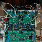
OK some photo of the third set that I build using the same components that I provide in the kit but with modications above to have a great sounding DAC:


