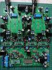
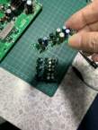
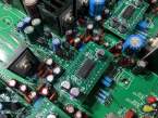
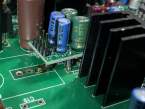
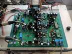
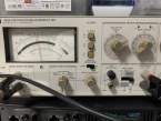
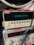
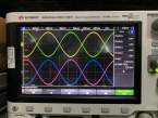
The Zen I/V was posted by Mr. Nelson Pass back in 2010. I have not enough time to try that due to my work location change and far away from my equipment. I am back home since 2021 and now it is time to try out the Zen I/V. Below is the photos of the Zen IV that I put on the D1V33 board and so far the result is very positive. The distortion for SE measurement can be down to 0.002% to 0.004%, in fact that is the distortion spec of the DAC chip. Here is the information sharing for anyone interested to comment.
- Rail voltage is only +/-20V as it is the limit of the current D1V33 board default supply.
- Use Drain resistor of 1.5k ohm due to limit of the rail voltage and thus give a Vd about 7V for jfet Idss of about 8mA. This is compromise due to Rail voltage max at 20V.
- Use daughter boards to put on top of original jfet IV locations. Since the pins for supply, input and output are not the same, thus I have to design 4 similar boards with different locations of the pins. The boards are names #1 ~ #4 for identification. Daughter Board is connected to main board via pins, some holes are not really on top and thus the pin has to be soldered a bit tilted (best locations of pins).
- Emitter follower is added to the Zen I/V with a pair of transistors to buffer the output to have lower output impedance. The distortion so far do not see any degrade in readings. In fact jfets pairs can be used but it will increase the cost!
- SMD resistors 1206 or MELF 1/4 W and capacitors 0805 are used on top and bottom of boards to make the board as small as possible.
- Tough job is to remove the original Jfet IV parts on the main board and it is helped by a de-solder station make by YiHua 948 (about US$60). SMD part is soldered with hot air gun also YiHua 8786D 2-in-1 station (about US%65). Really handy tools and cheap!
- I still left some pcbs and thus those interested, I can send to them with cost of SGD$20 for each set (include paypal and shipping cost). Sorry I do not have any more K170/J74 match pairs for sell!
My version of Zen I/V circuit: D1_V2_2_ZenIV_ckt
3D view of the Zen I/V board: D1_V2_2_ZenIV_3D
