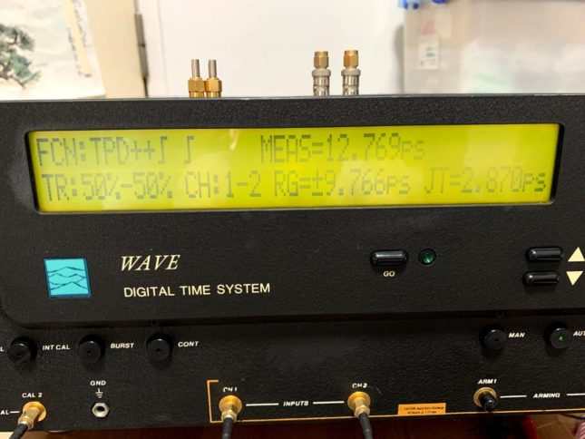
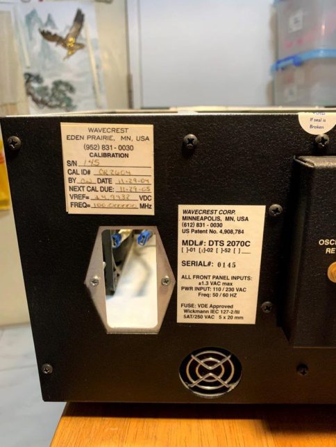
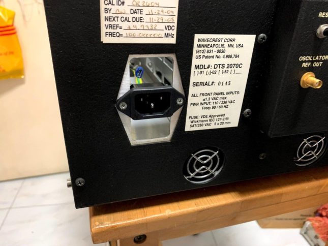
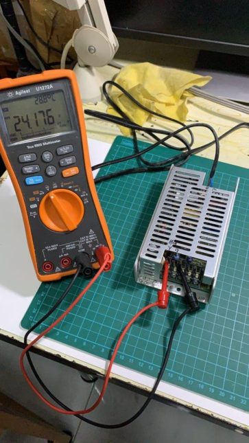
As in Photo, the IEC socket is missing due to burnt about 10 years ago. Since then no repair attempt is done as I am not using that very often. Until recently I have more time at home and now here is the summary of repair done:
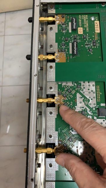
It took about two days to repair the set due to two power supply issue. To remove the supply is not easy as the bottom main board must be removed first! There are SMA + 6 screws for main board. Plus there are shield at the input socket connected by 9 screws with shielding plates hiding below the display module!
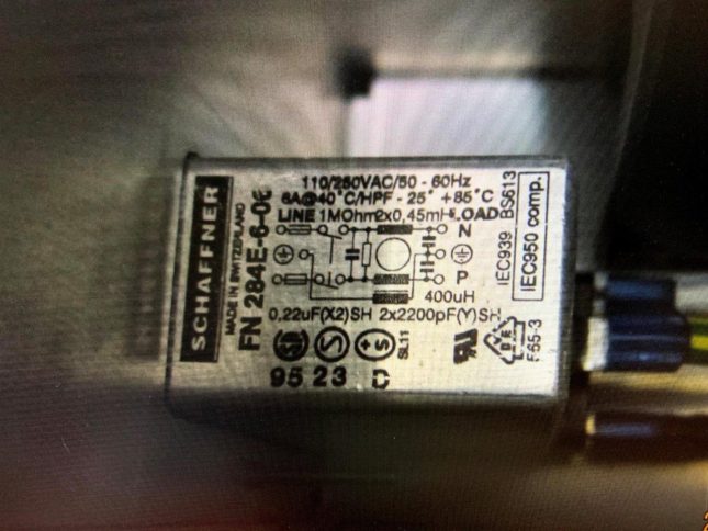
- The IEC socket was replace by normal socket without filter for use first. The original FN-284E-06 part cost US$40 per!!! Internal wire is rerouted so that it can reach the IEC socket near the rear panel.
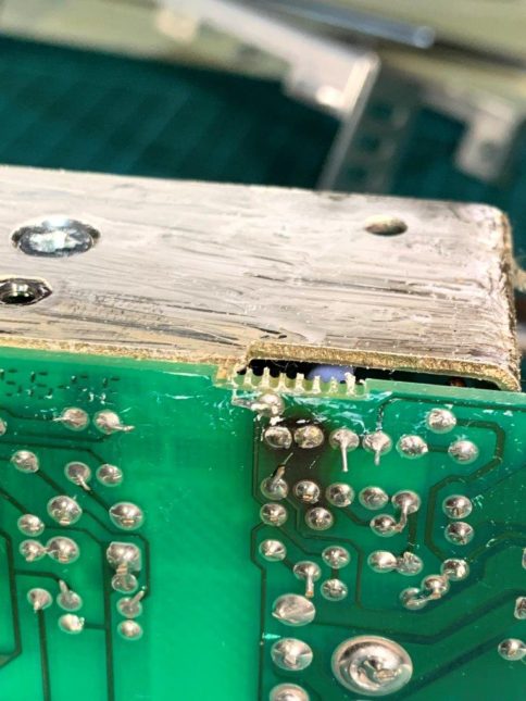
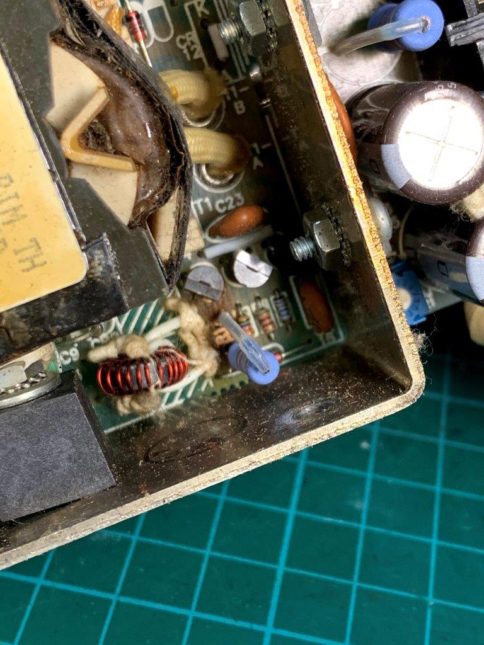
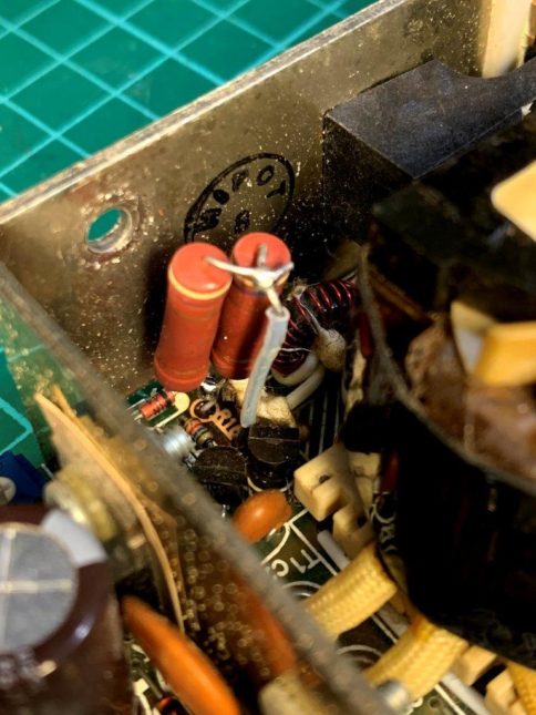
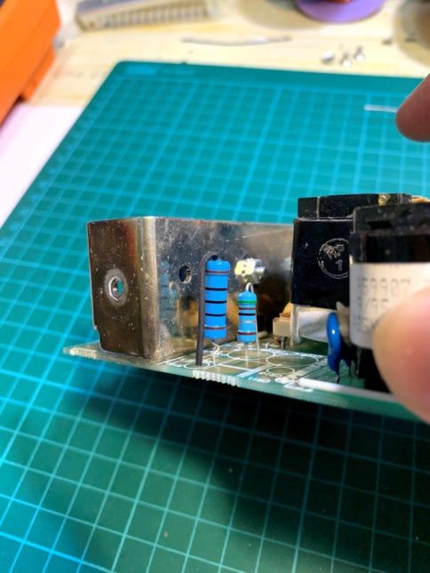
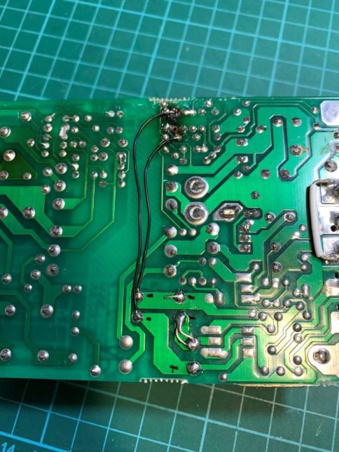
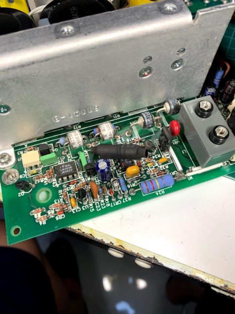
- 24 V supplier (smaller) is taken out for visual inspection but see a resistor has overheated and make the PCB darken! Blue resistor is remove with (Orange White Brown) 390ohm but actual measured is 90 ohm! Attempt to put two 470 ohm in parallel to same location but pad already peel off ! After repaired the big supply, burnt in for about 3 minutes cause the 24V supply voltage drop and give switching mechanical noise! Second attempt is to relocated the Blue resistor to other side by two wires and use 150 ohm resistors (50 + 100). After that is works fine. Loading test show is can do up to 1.5A with no issue. Also switch up and down time is faster.
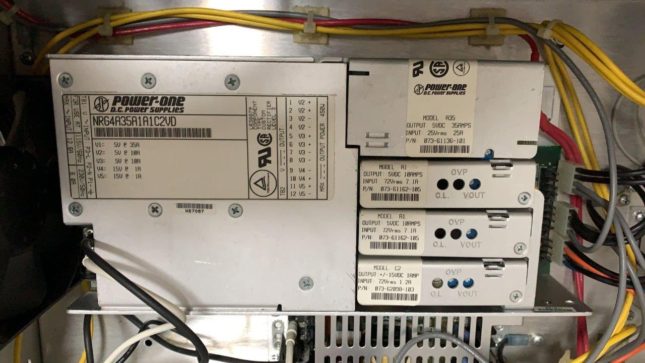
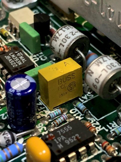
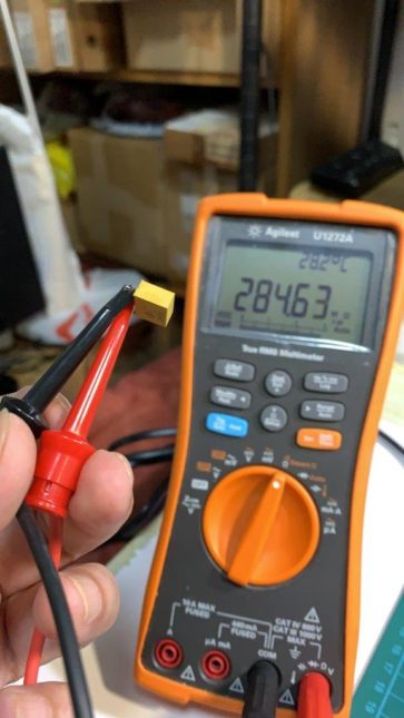
- Big supply is total dead with no output for all rails 5V, -5V, -5V, +15V and -15V. Trace the board and found the control ICs are with no power. Initial suspect is the small transformer got issue. Later measure the resistance still show some value. Further trace the supply to small transformer power is ground no return path from + high DC voltage to ground. Finally trace to the YELLOW fuse F2 BUSS PCC part. IN fact the fuse is put in the ground return path which is rated 1/2A fast blow type. To get replacement, the cost is 2.5USD each and take time. I decide to use the leaded type and shrink wrap it for insulation as replacement. I have other fuse but only rated 200mA slow but worry it will fail after some time use.
- After power Wave set for an hour, do internal CAL and then external CAL. The timing is not able to fully 100% meet spec but very very close or marginal failed only. Anyway it may be due to calibration variations as I do not own the original shorts cap from Wave but use only 50 ohm termination for external calibration.
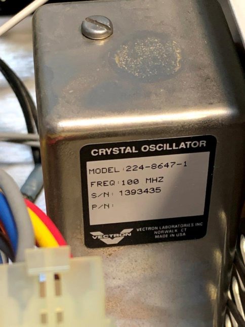
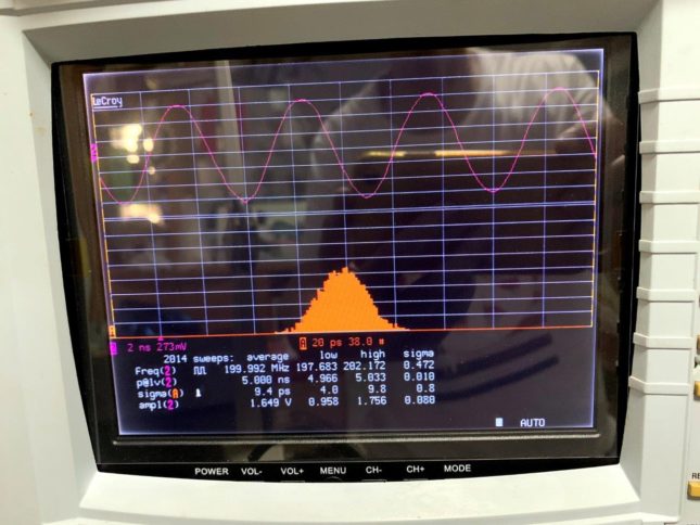
- The last picture show the 200MHz cal signal feed to Lecroy scope to get about 10ps jitter. The OCXO in the Wave is make by Vectron and claims to be about 3 ps jitter! It is not far but quite close!
