I have owned this equipment for few years and recently I find that the Digital input from BNC for channel I and II is not working properly. The symptoms are summary as below:
1. Channel I level cannot detect and thus refuse to do any measurement. Channel II can detect signal and do measurment.
2. The 75 ohm and Hi-Z switch is not functioning. For XLR input, the 110 ohm or Hi-Z is able to be selected and hear relay “click”.
3. When Gen Mon is selected, no measurement for both channels.
After checking the signal path of all digital signals using the generator as the digital source, it seems that the circuit is all working fine. On the front panel connector pcb, there is a MAX310 multiplexter to select different input connector and signals. Pin 15, 16 and 17 are address input A0, A1 and A2. In XLR mode, the voltages are solidly at ground level but at BNC mode, the pin A0 is like floating.
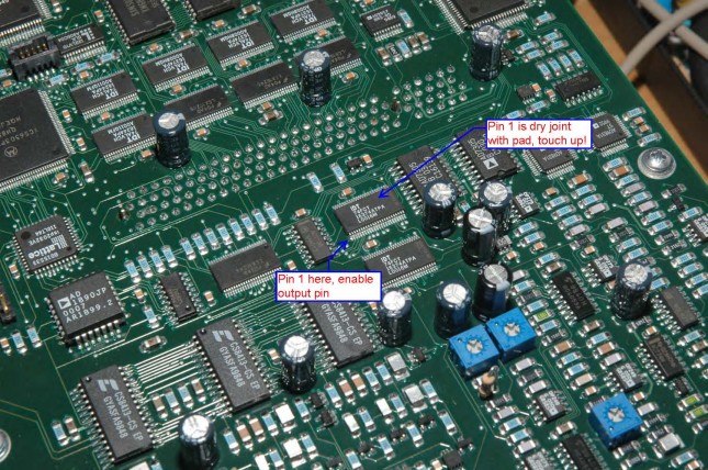
After spending hours of tracing the path (It is a multi layer pcb and thus the trace is not on top or bottom and I do not have a service manual of this equipment!) from the connectors of the main board, it was found that the address bus A0 to A3 is connected to an IC 74FCT16374AT – Pin 2, 3 and 5. Since XLR mode is working, thus there is no connection issue for this three pins. Pin 1 of 74FCT16374AT is the Enable pin of these three output address and thus I use a scope probe pin to check on this voltage. When I touch the pin 1, I hear a relay “click” sound and then the measurement of input digital signal is back to normal. When I remove the probe, the issue is back again! After I check connection of pin 1 using multimeter, the pin seems to be not connected to the pad due to dry joint (visually I cannot see any issue!). So the problem is removed after touching up the pin 1 of this IC with some solder paste. Here I attached a photo for those people who may have similar problem as my equipment.
