FET Audio | Hi-End Audio & Electronics DIY Electronics & Repair

July 7, 2012

New FDA-1B Full Balance PCM1794A DIY DAC kit

Filed under: DAC,Shop — Spencer @ 6:18 pm

See Store page for NEW PRICES.  http://www.fetaudio.com/store

.

This FDA-1B PCM1794A DAC is an upgraded version of the obsolete FDA-1 Single Ended DAC.  FDA-1B has been developing for 1.5 years since FDA-1 was selling. More than 7 version PCBs have been tested before launching to DIYers. It has improved all the weaknesses of FDA-1 and added additional features and functions to enhance the sonic performance and flexibility of the design. Thus it is a more complete and mature design with separate Front Panel control board, I2S input via RJ45 socket and optional ASRC function via daughter board plug-in!

.

Since it is a DIY DAC and thus most of the parts are selected to be through-hole parts except the ICs and some film capacitors.  In fact most of the film capacitors pad are designed with both SMT (Surface Mount Technology) and TH (Through Hole) pads/holes and thus user can make a change in case better parts is available on hand.  In the I/V section, all TH resistors and some filter capacitors are also provided with a SMT pads in case people want to try the SMT parts.  For the digital section TH resistor pads can also be soldered with a 0805 SMT resistor due to its pitch is 2.54mm. Thus this PCB design is really remarkable and flexible for DIYers to experiment with different types of part for sound tuning!

.

For the Front Panel control board, it is mainly SMT parts with TH for LEDs and sockets.  Thus it provides a good basic training for all DIYers for SMT soldering.  In fact, SMT parts (with size 0603 and above) are easier and faster to hand solder than TH parts after managing the skills.  What you need is just a 5x magnify glass with stand, small head tweezers, 0.4mm to 0.5mm diameter solder wire and your two stable hands.

.

New update manual Rev 2: FDA-1B DAC Manual_r2a

This file help to locate all difficult to find resistors, capacitors and diodes: 15c-Part_Location

Go to Store page if you want to buy this kit.

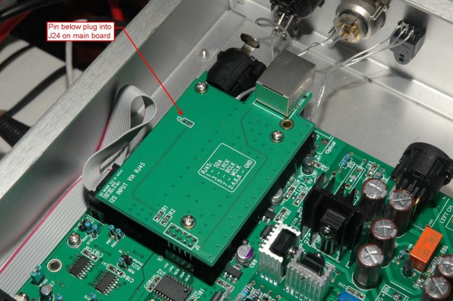
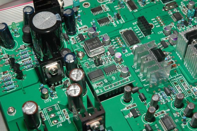
Here is some photos of the FDA-1B DAC kit.

Note that ONE type of I2S input daughter board with RJ45 socket will be provided free.  There are 3 type RJ45 pin assignment boards that can be selected during order – Fetaudio, Kingrex and M2Tech.

The pin assignment can be found in attached document:

RX7-silk1

Related Images:

May 15, 2012

New FDA-1B ASRC Board

Filed under: DAC — Spencer @ 1:28 am

The daughter board is to be used with FDA-1B DAC.  It can use two chips – SRC4192 or AD1896.  Note that the price of this FDA-1B ASRC board is HK$800 (about US$100).  It will be fully assembled and tested before shipment.

.

With SRC4192 chip, the output sample frequency can be set to 48k, 96k or 192k by two jumpers.  With AD1896 chip, the output sample frequency can be selected at 96k, 48k or 32k.


An XO with frequency 24.576MHz is used as the master clock in the ASRC board.  Through hole type DIP or 5x7mm SMT type XO can be soldered on the pcb but a DIP XO will be provided by default as shown above.  Only 3v3 XO can be used.

.

Circuit: FDA-1B ASRC Ckt

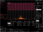
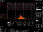
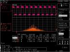
Jitter measurement is show in below 3 charts for SRC4192 chips:


Related Images:

April 30, 2012

New FDA-1B Development History

Filed under: DAC — Spencer @ 12:39 pm

Here is the history of the past versions of FDA-1B for past 1.5 years.  I am still searching for the photo of V3 but I believe I did not take any photo of it due to the poorly design of the digital input selection.

.

During the development process in V1, many regulators had been tested on the PCM1794A for both the 3.3V and 5V regulators and eventually the simple LM317T plus AMS1117 regulators were selected for it most balance sonic performance.  The lesson learnt here is that expensive and high performance low noise regulator might not sound best in this design.  Also various SMT and Through-hole transistors were tested.  Resistors and capacitors were also tested at various locations to see how much it will affect the sound.  Of course the most important evaluation were the ASRC chips like AD1896, SRC4192 and CS8421.  After many hours of listening, AD1896 with 96k Fs output is rated the best sound ASRC chip in this platform.  For the digital input on the 4th selection – I2S/USB, PCM2707 (USB 16bit 48k) was evaluated but the sound was just too ordinary.  Later XMOS USB reference design was plug into the I2S input and the sound is just too good to be true.  Other receiver chips were evaluated like DIR9001, WM8804, WM8805 and CS8416.  The best sound chip is WM8804, then WM8805, then CS8416 and last is DIR9001.  In fact I would say the WM8804 and XMOS reference design sound equally good in FDA-1B. Thus I have no urgency to move to USB yet as the CD-PRO2 transport and the Logitech Classic media player is providing digital source music with no issue at all in both V13 and V15c versions.

.

In the final version V13, it is basically a SMT version mainly designed for mass production.  Then a through-hole (TH) version V15c was created for the DIY market.  So here is why I start to sell the FDA-1B DIY DAC from April 2012.

FDA-1B Rev History – Summary of the revision change history

V1 – Through-Hole version – evaluate regulators, ASRC and 4th digital input + CS8416

V2 – Convert to SMT in digital section + CS8416

V3 – SMT and WM8804 with digital input switch.

V4 – Layout improvement, use relay for digital input select + WM8804

V5 – Layout improvement

V10 – Layout improvement

V13 – Improve I2S bus timing, add SMT pads for IV section; full SMT version for mass production

V15c – DIY version for DIY market


Related Images:

January 14, 2012

FDA-1 PCM1794A DAC Kit Revision 6 Manual

Filed under: DAC — Spencer @ 6:02 pm

Note that a new revision manual is released today.  The new revision added two attachment 6 & 7 total 5 pages at the end of the manual.  Attachment 6 is the Balance mode external I2S connection and attachment 7 is the rear panel dimensions.

FDA-1 PCM1794A DAC Manual_r6

.

Note that this FDA-1 DAC kit is all SOLD out! 

Related Images:

January 9, 2012

XMOS USB Audio 2.0 Reference Design Jitter Measurement

Filed under: DAC,Sources — Spencer @ 10:06 pm

The XMOS demo board sold for $149 in digikey.  The firmware need to be loaded before the board can be used.  There is a digital out from the USB 2.0 demo board and thus it will be a easy interface from USB to FDA-1 optical input.  What you need to do is to get an optical cable to link up output of demo board and input of FDA-1 Toslink.  I have tested this mode and the sound is better than using Ti PCM2707 USB receiver with I2S output.

.

On board, there is a I2S connector and thus the clock jitter measurement is taken at the MCLK, BCLK, LRCLK locations.  The jitter at MCLK from 48k to 192k Fs is from 10 to 13 pico second respectively which are excellent.  In fact the MCLK is taken directly from the onboard crystal oscillator after the buffer logic IC.  For jitter at other clock like BCLK (Bit Clock) and LRCLK (Word Clock, Fs), they are as high as 800 pS or above.  For any DAC using the MCLK as the clocking reference (like FDA-1), the result should be very good.

Attached is the document of jitter measurement for reference:

Jitter measurement by Lecroy DDA-120

From all the measurement, the lowest jitter mode is to set the output of the USB 2.0 at 24 bit with 48k Fs.

With a more accurate period jitter machine Wavecrest DTS-2070C, the jitter at MCLK is measured at only 4.6ps.  See attached document:

Jitter measurement by Wavecrest DTS-2070C

Related Images:

« Newer PostsOlder Posts »

Powered by WordPress